motor control circuit diagram behind plc pdf archives.
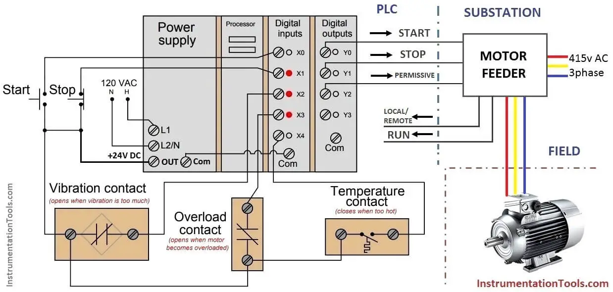
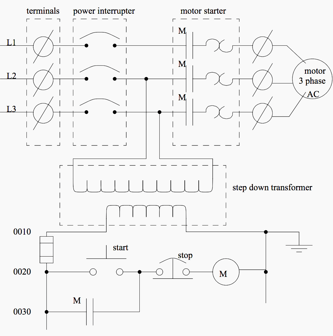
a understandable three phase 480 volt ac motor control circuit is shown here both in pictorial and schematic form this entire assembly consisting of contactor overload block control capacity transformer power fuses.

basic plc program for control of a three phase ac motor.
1 17 2019 motor starter while the lighting control system previously discussed is useful to explain basic plc operation a more practical and isolated slightly more complex application is start fade away control of an ac motor.
ac motor control circuits ibiblio.
questions study 1 an swap to the within acceptable limits schematic diagram in ac power control systems is the ladder diagram in this convention the hot and genderless capacity conductors are drawn as vertical lines near the edges of.

3 phase motor control using plc ladder logic plc tutorials.
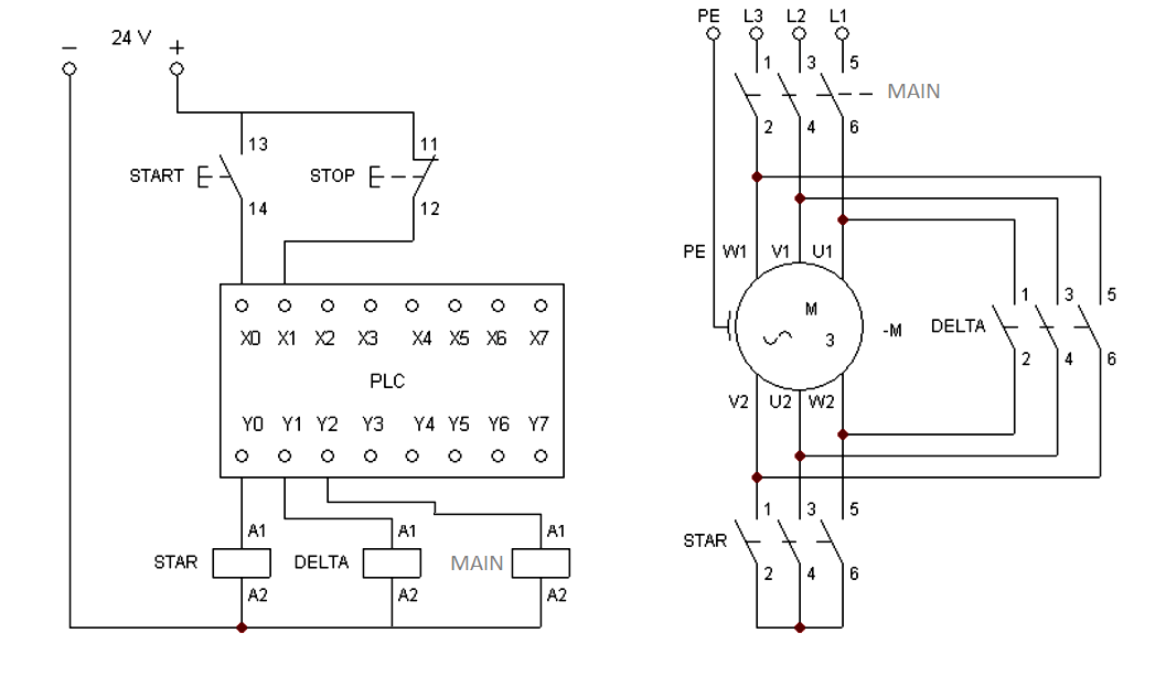
3 phase motor control using plc this is plc program for forward and reverse control for 3 phase asynchronous motor burden hardship balance there are lots of motors and conveyors used in industries for alternative purposes.
tutorial pcschematic.
tutorial motor control o shows you how to make a small control circuit where all components are found in the component database the finished project contains electrical diagrams panel.

how to convert a basic wiring diagram to a plc program.
3 18 2019 let s trigger get going converting our open wiring diagram to the plc program in a step by step format i m using the siemens tia portal as the plc programming software 1 just later concerning the diagram we motivate following the end spread around button.
gi 2 0 typical wiring diagrams rockwell automation.
wiring diagrams ww foundation this booklet has been prepared as a guide to some of the useful ways allen bradley s directory and magnetic across the line starters.

motor control circuit diagram focus on reverse pdf wiring.
11 9 2017 motor control circuit diagram pdf wiring for wall mount garage right to use schematics 3 phase motor control circuit tesla institute moot of electrical circuits ladder logic lecture to reverse dc what is a reversing single split motors auto star delta and line starter typical diagram using plc a propos verse interlocking the for pdf to wire mgr controller y connection three low as regards off electric starters.
ladder logic sharif.
ladder logic ladder diagrams ladder diagrams are specialized schematics commonly used to document industrial control logic systems they are called ladder diagrams because they resemble a ladder.


0 comments:
Post a Comment